https://lasma.eu/en/search/products
Current transducer is a galvanically isolated sensor that converts AC or DC current into a standardized voltage or current signal (0–10 V or 4–20 mA). This type of signal is safe, accurate, and directly interpretable by PLCs (programmable logic controllers), SCADA systems, and energy monitoring platforms.
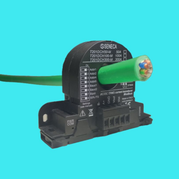
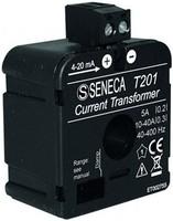
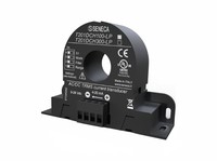
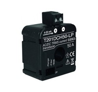
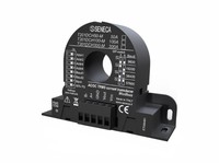
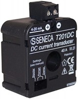
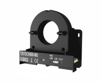
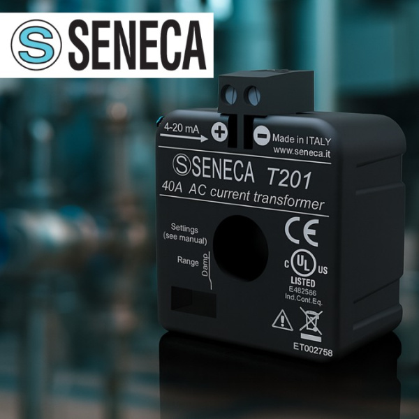
Seneca T201 is a series of Hall effect and TRMS-based current transducers that includes UL-certified models. These transducers offer a true “plug-and-measure” solution with no need for costly integration or external power supplies.
A current transducer converts primary current into a galvanically isolated, standardized signal (4–20 mA or 0–10 V). Unlike a basic current transformer, a modern transducer simultaneously:
This functionality enables reliable monitoring of motors, inverters, and DC busbars without the need for expensive optical or Rogowski-type isolation.
 Using a current transducer is not just a technical choice — it is a strategic decision that directly impacts the reliability of automation systems, energy metering quality, and workplace safety. Small and mid-sized enterprises (SMEs) often seek solutions that are easy to integrate, safe to operate, and cost-effective to maintain.
Current transducers offer significant added value, especially in light of modern requirements for data traceability and energy efficiency improvements.
Energy efficiency — A 4–20 mA signal can directly power a PLC analog input, eliminating the need for external power sources and reducing system-wide energy consumption.
Maintenance simplicity — DIP switches or configuration software allow quick adjustment of measurement ranges and filters, reducing downtime and reconfiguration costs.
Enhanced safety — Measurements are performed without contact with exposed high-voltage lines, significantly reducing the risk of electric shock or fire hazards.
Data quality for decision-making — Accurate TRMS measurements provide a reliable foundation for analyzing production KPIs, energy usage, and equipment behavior, enabling better decisions and traceable compliance with quality management systems.
In summary, current transducers help businesses achieve efficiency, sustainability, and quality goals more easily — with technology designed to fit limited budgets and constrained engineering resources.
When choosing a current transducer technology, it's essential to understand the differences between the available options on the market. The T201 series combines several modern technologies in a compact format, but to appreciate its advantages, it's helpful to compare it with the most commonly used principles:
CTs work best in simple, stable AC lines where cost and simplicity are the primary concerns.
This approach is especially suitable for modern production environments where fluctuating loads and high precision are the norm.
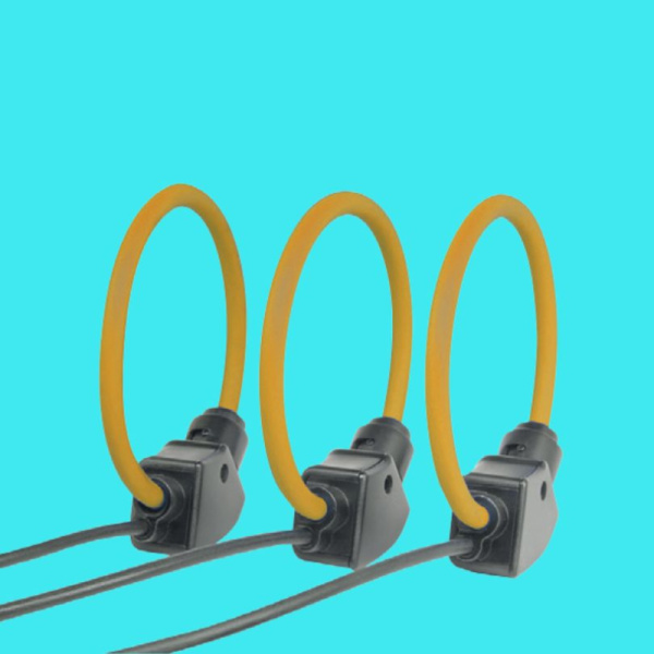
 Rogowski Coil – a coreless measurement principle based on electromagnetic induction, ideal for:
However, Rogowski systems typically:
Considering all factors, Hall effect transducers as used in the T201 series are often the most practical solution for small and mid-sized enterprises. They combine the accuracy of CTs, DC compatibility, and the flexibility of Rogowski coils — delivering a balanced trade-off between performance, cost, and ease of installation.
This technical choice enables businesses to scale their automation and monitoring infrastructure with confidence — without sacrificing data quality or operational reliability, both of which are crucial for high-value decision-making.
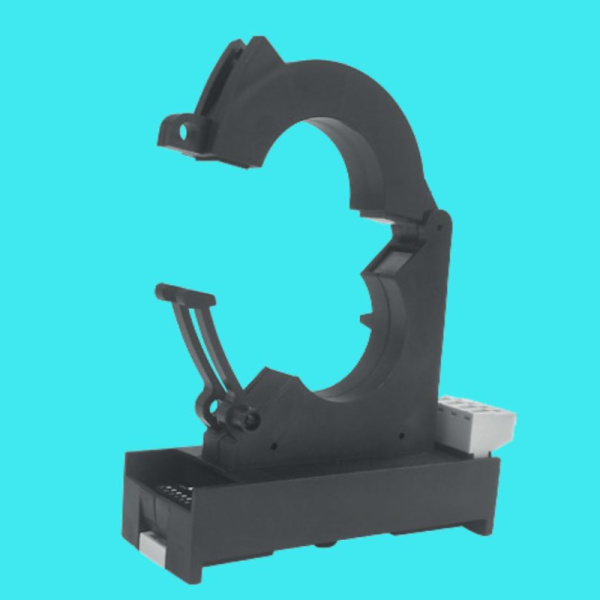
The T201 series transducers are designed for fast and safe integration into industrial automation environments. Their mounting on standard 35 mm DIN rails and connection via removable screw terminals significantly reduces installation time — typically under 10 minutes per measurement point. The following outlines the typical implementation steps:
Planning – identify all measurement points such as electric motors, variable frequency drives, power buses, or DC distribution rails. Determine the nominal current range for each circuit (e.g., ±100 A, ±300 A), considering both normal operation and potential overloads.
Model Selection – choose the appropriate T201 model based on the following criteria:
-MU or -M models if Modbus RTU protocol is required.Control Cabinet Preparation – ensure adequate ventilation space, especially for high-current models (≥300 A). It is recommended to maintain at least 50 mm of free air around the sensor to avoid thermal buildup and maintain measurement accuracy.
Wiring – follow the correct polarity: the direction of current flow is indicated on the sensor label (typically marked with an arrow or "IN"/"OUT"). Connect the supply voltage as specified for the model (e.g., 12–28 V DC).
DIP Switches / EASY Setup – configure the device by:
-M or -MU versions.PLC Configuration – apply scaling to the PLC analog inputs according to the sensor’s specifications, for example:
Ensure your control software or SCADA platform properly interprets these values — this is essential for accurate KPI calculation and energy performance reporting.