PID control with Invertek Drives variable frequency drive
May 25, 2020
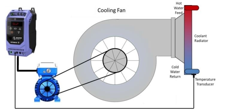
PID control is one of the most widely used management methods in feedback systems, so it is important to be able to set it up. A widely used PID control is in pressure and temperature control systems.
How to set up Invertek Drive VDF in PID control mode?
Follow the steps below or watch the VIDEO tutorial in the LINKS section!
- Connect the motor to the VDF
- Connect power supply to the VDF
- In parameter P-01 enter the maximum operating frequency (50 Hz in most of cases)
- In parameter P-02 enter the minimum operating frequency
- In parameter P-03 enter the acceleration time
- In parameter P-04 enter the braking time
- In parameter P-07 enter the nominal motor voltage (230 or 400V)
- In parameter P-08 enter the nominal motor current
- In parameter P-09 enter the nominal motor frequency (50 or 60 Hz)
- In parameter P-10 enter the nominal motor speed (step is optional, when entering values greater than 0, P-01 and P-02 values are reflected ir revolution per minute and operating speed will not be displayed at Hz but in rev./min)
- In parameter P-12 enter value 5 (PID control)
- In parameter P-14 enter 201 (approach in addition to parameters)
- In parameter P-16 enter the sensor signal type (4-20mA, 0-10V, etc.)
- In parameter P-30 enter Auto-4
- In parameter P-41 the impact of the input signal on motor perfomance may be increased if necessary
- In parameter P-42 the impact of the input signal on motor performance may be slowed down of necessary
- The parameter P-43 sets up direct or indirect action (If the value is 0, when signal value falls, the motor speed will increase. If the value is 1, when signal value falls, the motor speed will decrease)
- In parameter P-44 enter value 0
- In parameter P-45 enter the desired temperature or pressure level then needs to be adjusted on a scale from 0 to 100
- In parameter P-46 enter value 1
- Connect the sensor to the terminals 6 and 7
- Connect terminals 1 and 2
https://lasma.eu/en/add-to-basket
Products
[115]
1
1
1
5+
https://lasma.eu
Code: ODE32400583F42
On site:
5+
pcs
On site: 0
Supplier: TBC
1
1
1
5+
https://lasma.eu
Code: ODE33401403F42
On site:
5+
pcs
On site: 0
Supplier: TBC